The HKL-2000 program uses a parameter file, a so-called site file or def.site file, which contains unique parameters describing the detector/goniostat system:
- X-ray detector and goniostat information
- X and Y coordinates of the direct beam position on the detector
- Goniostat misalignment
- Direction of rotation
- Detector orientation
- X-ray beam properties
- Expected suffix for data files arising from this site (e.g. *.img, or *.osc, etc.)
This information is stored in the $HKLDIR directory (usually /usr/local/hklint directory) as a series of subdirectories; one for each detector/goniostat system. In addition, the user may create (by choosing New Site) a default site file for any detector recognized by the HKL-2000 program. This site can be modified later.
For synchrotron data processing, the appropriate site file should be obtained from the synchrotron beam-line staff.
We can help to make the initial def.site file for a home detector/goniostat system.
A description of test data for various detector/goniostat combinations has been described further down. For new licenses, this service is free and is a part of the license activation.
Your use of the HKL-2000 software may be impaired by the lack of a proper site file.
It is important to collect a good data set as the goal here is not to solve a Lysozyme structure, but to find detector and goniostat imperfections. If we start from good test data, we can evaluate the system and generate the parameter file, which in turn will help to process data and solve the structure of unknown proteins.
For comparison, we would like to provide examples of ‘good’ data and ‘bad’ data.
If your images look like those in Fig. 1, congratulations, you may go ahead and collect the whole dataset.
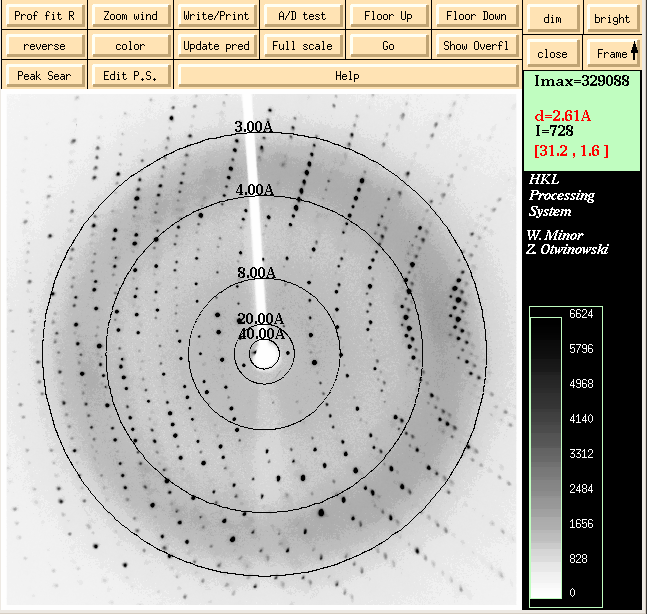
Fig. 1. Well diffracting, single Lysozyme crystal. Well resolved diffraction spots.
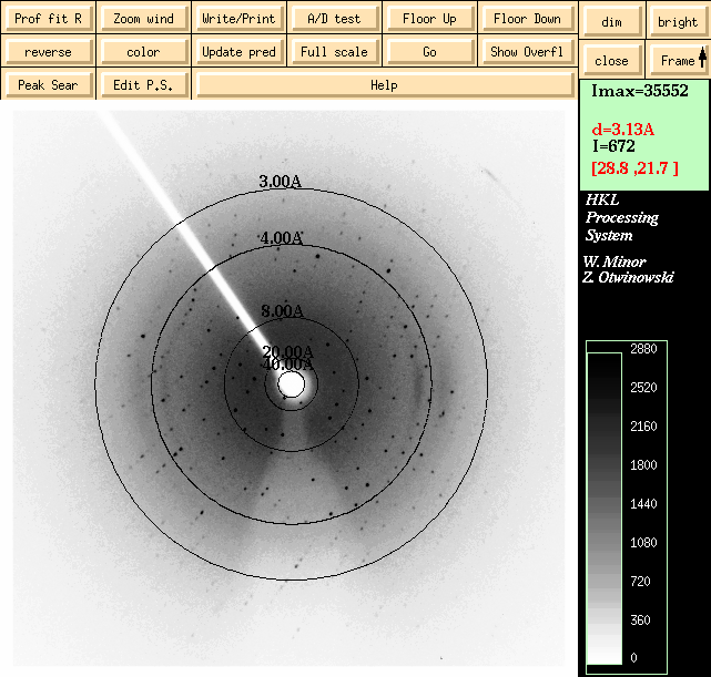
Fig. 2. In this example the crystal does not diffract to high resolution. In this case, goniostat and detector distortion parameters resulting from the calibration may be sub-optimal.
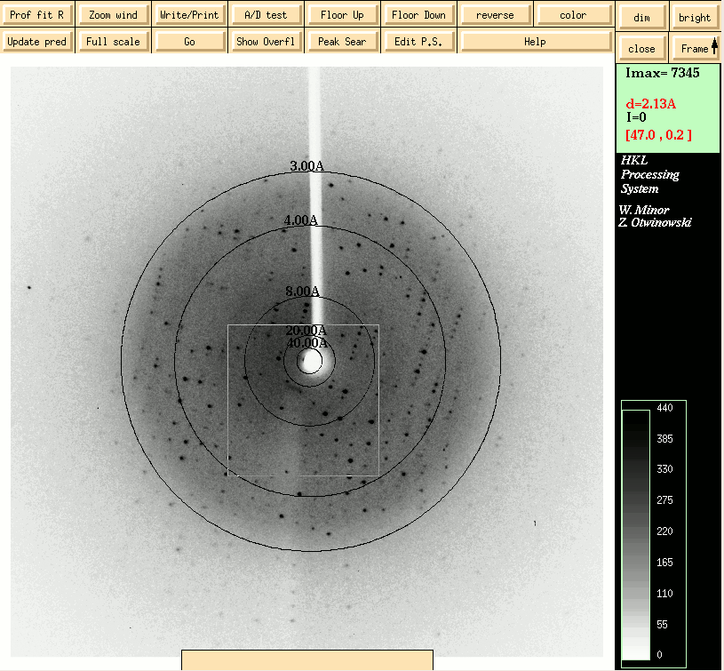
Fig. 3. The diffraction spots are not singular, possibly due to a poorly frozen crystal, see also Fig. 4.
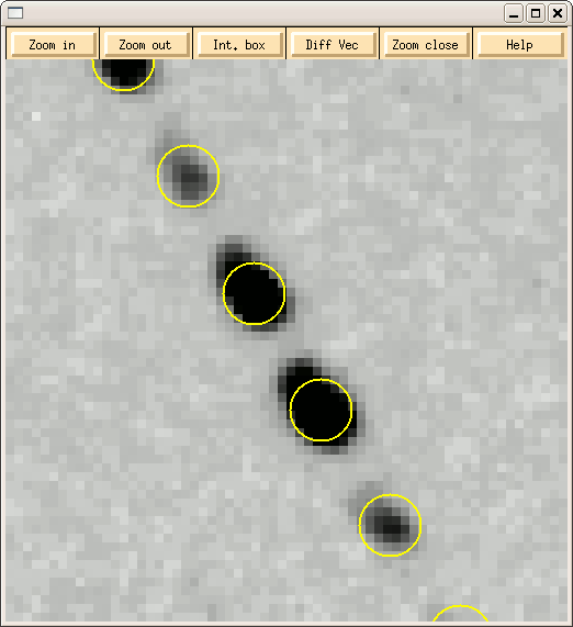
It is also worthwhile to open a ZOOM window and look carefully at the individual diffraction spots. For example, careful inspection of Fig. 3 shows an imperfect shape of diffraction spots. This will affect the determination of ‘the error positional’ parameter for this particular detector.
Fig. 4. The zoom window shows the enlarged, elongated spots.
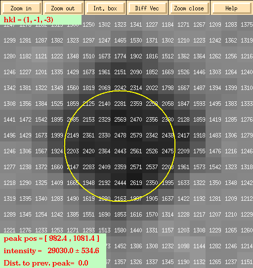
Fig. 5. This is an example of a very weak reflection. There is not much difference between the background and the diffraction spot. Weak diffraction often indicates a poor intensity of an incoming beam usually due to a misalignment of mirrors.
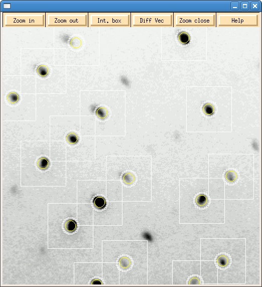
Fig. 6a. Multiple crystals in the beam.
Finally the very worst:
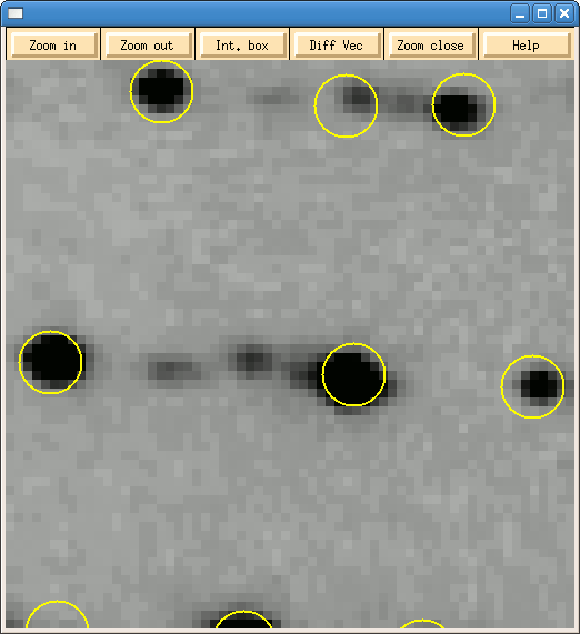
Fig. 6b Multiple crystals in the beam.
HKL suite of programs can process these data just fine, however, the accuracy of the parameters in the def.site file will be affected by sub-optimal calibration data.